One big thing I’ve been working on lately is bitbox! Bitbox started as just a clever idea, but it was just so interesting that I had to make it :) Bitbox is essentially a tiny music player that will play 8-bit music – sorta like a boombox, but a bit smaller ;)
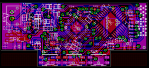
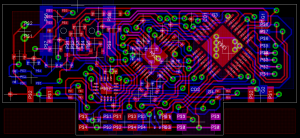
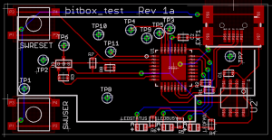
I still have some software work ahead of me, but here’s the (nearly) final circuit board:
(I say nearly final because I did go on to make some tweaks after taking this image)
Read on for a train of WIP images and more information…
Bitbox has been a bit of a long standing project for me, so I’m not sure why now seemed like a good idea to finish it – Perhaps it was because I ran into the NXP LPC1343 ARM microcontrollers, which are pretty incredible chips, and rather well suited to this task.
The architecture is pretty straightforward but there are some messy parts in the design; The DAC/Amplifier chip I’m using receives the I2S protocol for audio data (and some variants), and the ARM doesn’t actually produce it nicely – but I have rigged up some timer outputs and can generate the signals that way (And I’ll even be able to use the SPI fifo buffer as a outgoing sample buffer!)
This will be my first project trying to manage a rechargable battery, so hopefully I didn’t make too many mistakes there :) I have some FETs and diodes making sure current won’t flow the wrong way when running off of either the battery or USB.
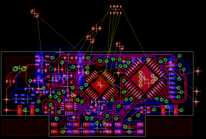
Overall this was a pretty complex design, and routing the board (within the space requirements I set out with) has been pretty challenging. It looks pretty good though, I’ll post more on this once I get some PCBs back and populated.
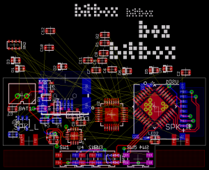
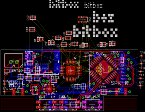
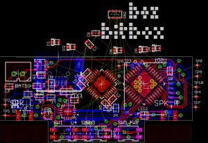
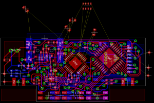
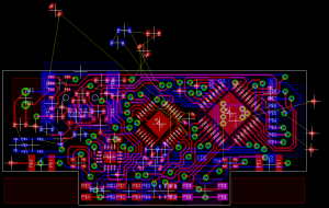
On with WIP images!
(Magic happens)
(At this point you can see the left side of the board shift left a tiny bit, as I work to make more space in the middle)
As I’m feeling a bit adventurous (and not really interested in soldering a bundle of wires to program these), I’m also building a test jig! Still working on the exact design, but I’m planning to use a lot of laser cut acrylic, and I’ve designed another PCB to sit on top and do the programming. Given the signals I’ve broken out to test points, it should be possible to do a more comprehensive test in the future by swapping out the test PCB (but still not a complete test – I’ll have to work on improving testability of my designs.)
Questions? Comments? Let me know!
RSS feed for comments on this post. | TrackBack URI
November 15th, 2010 at 3:18 am
> I say nearly final because I did go on to make
> some tweaks after taking this image
Are there 2 incomplete routes in that image?
November 15th, 2010 at 11:48 am
Indeed there are 2 incomplete routes, but I didn’t change them :) They belong to zero-ohm resistors, where I decided it would be far simpler just to leave an incomplete route instead of separating the signal into the halves that should appear on either side of the resistor bridge.