Here’s the first installment of my weekly project report thing :) Wish me luck!
So, not terribly long ago I decided it was really time to give microcontrollers another go; My history with microcontrollers in general has been a little sketchy, because not only are they pretty limited systems, but they don’t really allow a lot of creativity in solving your problems. Being mostly self-taught on ARM and x86 CPU architectures, the little 8-bit uCs generally seemed more like a pain than anything else.
However, I was determined not to let my history deter me, and to try again. I ordered some AVR DIP chips for prototyping and a serial programming cable. Unforuntately, like so many well laid out plans, this didn’t wind up working out – not knowing too much about the AVR landscape, I had inadvertently ordered a serial programmer that requires an actual native serial port to work (it wouldn’t do anything with my USB-serial converter… And seriously, who has a native serial port around these days?)
Being incredibly stubborn and unwilling to wait further to order yet another programmer, I decided to take matters into my own hands – After reading the AVR documentation on programming their chips (which is actually quite good), I put together a small CPLD based programmer which has served my needs. Read on for the full details…
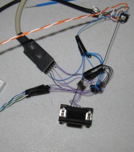
The original version of the programmer was a tangled ball of wirewrap wire, tightly coupling the core components, and was fortunately soldered well enough to hold together for several weeks before the first PCB arrived. I built the programmer out of materials I had readily lying around, it consists of: A 3.3V regulator (At the time, I was going to run the AVR chips at 5V – and my CPLD is 3.3V with 5V tolerant IO), a CPLD (XC9572XL), a 50MHz clock generator, and a MAX3232 equivalent serial level shifter (and a few caps for good measure). I wrote some basic VHDL to speak serial and accept some basic commands to control some pins as GPIO, and then a powershell script (yes, a powershell script) that interfaced the serial port and performed the high level programming commands. It didn’t take too terribly long, and it did finally work! I got my AVR to blink an LED, such a worthy task of all this effort :)
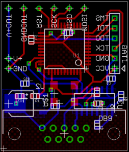
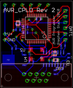
Below is the evolution of versions of this project – First the tangled mess; Second was the first PCB revision, it added an LED and had a few minor pcb errors; And third is the second PCB revision – which has 2 LEDs (one red, one green) for status.
(Can you spot the PCB errors in rev 1?)
Another hurdle that had to be overcome was that of programming speed – using the CPLD just as GPIO worked, but manually sending a byte for each clock transition was pretty slow and tedious. So I revisited the CPLD firmware and added another mode for AVR programming, It’s a special command that operates on the following 4 bytes: for each of these bytes it will automatically generate clock transitions in sync with the serial state machine, and also send back the data received from the chip (which is also in sync with the serial state machine). This makes programming the chip approximately 16 times faster than it was – it’s not as fast as it can be but it’s pretty quick and only limited by the serial connection speed at this point.
So, while this project hasn’t precisely been a necessary one, it has actually been pretty interesting and useful. One of the nice things about having a few GPIO pins around is that I’ve actually reused this for other things as well, like dumping a serial eeprom :) (in fact I even wound up using the 4-byte serial mode for the EEProm serial transfer as well, it’s pretty much just a 32bit serial mode) – And I imagine this device may come in handy in the future too for similar things (though, it will probably become obsolete around the time my current big project is done… I’ll leave that one to your imagination for now.)
And finally, this project did indeed serve my original goal, I’ve continued to do some development for the AVR uC platform, and while I still would prefer a much more beefy CPU, I have to admit that these little chips are pretty intelligent choices for small cheap projects that need something “smart” but don’t need much in the way of power. As such, I have a few projects based around them – and while I don’t have too many projects involving uCs at the moment, they are likely to get more attention in the future.
Okay! So that’s the first one; I hope you found this entertaining, and who knows where this will go next week :)
RSS feed for comments on this post. | TrackBack URI


May 17th, 2010 at 3:54 pm
“Can you spot the PCB errors in rev 1?”
. . . the backwards type? Please tell me it’s the backwards type, because otherwise I’ll feel like a dolt for understanding little else about this post. *grin*
May 18th, 2010 at 10:25 pm
Hehe, sorry :) I did change the displayed layers between the two so it’s not so obvious but the backwards type exists on both.. In this pcb design, the front and back copper layers are represented with red and blue in the image. Green are regions that exist on both and connect them together… For the most part electrically the boards are the same, but there are some differences :) I’m not telling what they are though… so someone will have to spot them ;)
May 21st, 2010 at 1:23 am
I’ve never been good at soldering and microcontrollers, but I can’t help having a flow of stupid gadgets coming to my mind whenever I see a PCB design… yours resurrected the idea of a wristwatch-GBA-buzzer companion for DSOrganise :P
Keep going ^_^
June 21st, 2010 at 10:34 am
Looks like you switched two pins at the D-Sub (pins 2 and 3). Also, in the first design, LED1 and R1 don’t seem to be connected properly. That’s all I could find.
June 21st, 2010 at 10:55 am
Ortwin: Nice – Indeed those are the two errors that I revved the PCB to fix (and just moved some things for convenience). Not much fun cutting traces and blue-wiring it.