This isn’t exactly what I had in mind with my last post (there’s another project coming up after this one), but it’ll do for now :)
I had an idea for a simple mechanical design for a quadrotor, and since I was already pretty interested in building one, that prompted me to go work on the design for it. Like with many things I do, I like to build the full stack in projects like these – so I’ve designed my own electronics for it as a first step. Some of the PCBs have come back from fabrication so I expect to make more progress with this pretty soon.
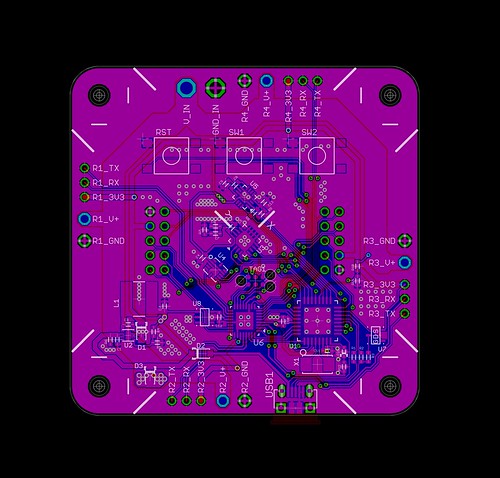
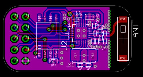
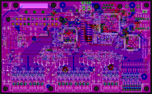
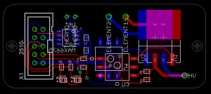
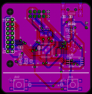
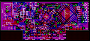
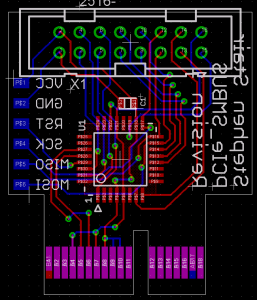
Some pictures from the PCB designs:
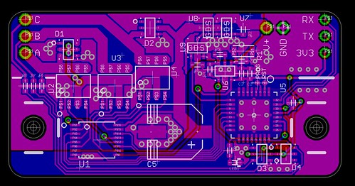
The three boards above are a speed controller to drive the motors, the main PCB that will collect sensor data and do control, and a plug-in module for the main PCB which has wireless (via Nordic RF chipset) and a flash chip for archiving sensor data / other general use.
For now, I’m just writing initial firmware and testing that things work, but once I confirm the design is viable I’m planning to release the design files for it.
Another interesting feature of this project is that I screen-recorded the PCB design process – I’m planning to edit the videos into timelapses and add some commentary on the thought process behind the design. I’ll post about these also once they’re released.
