Hi again,
As promised, this week’s project entry is much less entertaining;
I did attempt to get this project a bit further today but distractions have taken their toll. Expect this one to come up again in the future :)
So, not too long ago I had the bright idea to build a little USB stick; My motives at the time were apparently highly questionable, so I am here about a month later with a fairly limited use USB stick
One of my major goals behind this project was to have an excuse to work out the details of USB, and try some stuff out, which I’m still doing now. Once I get that done with, I will attempt to explain just how all that works; USB is a bit elaborate, but it’s increasingly interesting and important these days, as serial and parallel ports are becoming more rare. I have another project along these lines too, but it’s quite a bit more low-level.
For this post though, I’m just talking about the hardware design of this project.
The board was really quickly designed; I thought (for some reason) that it would be neat to have a little USB stick that had an RGB LED, and a speaker to output audio. So, that’s what I made :)
This stick is based around a Atmel ATMega32U2 microcontroller, which has built-in USB device support. It requires a pretty stable clock source in order to use USB, so I picked an 8MHz crystal for it. I found a reasonably cheap RGB LED on digikey, and added some passives, an op amp, and a tiny speaker I had around for sound.
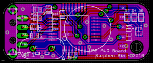
PCB design for the board (It looks confusing because I’ve included a lot of layers, but you don’t usually work with all of those layers on, you can just look at the front/back individually)
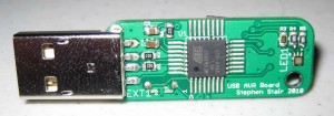
And, actual implementation of the board!
I’m sure you can see the mistakes in this one, but probably not quite all of them. Things to check for next time I make a really rushed design:
- Make sure TFQFP package reflects reality. Not sure how but my pads start at the very tip of the pins :) I must have been looking at the wrong package type for spacing info.
- Enhance font size on 0402 components (see the 2 tiny capacitors by the crystal? They’re C1 and C2 in the PCB design image.)
- Make sure crystal doesn’t overlap other components (fortunately the crystal body isn’t connected to anything, so it can be near / short against USB V+ without issue.)
- Pay closer attention to drill sizes. USB header shield doesn’t actually fit through the holes I designed it for. I have a caliper so these sorts of mistakes are just silly :)
Some other miscellaneous design notes
- This AVR has a 3 PWM channels based on one 16bit timer – this is being used for the RGB LED
- The audio output is a PWM channel on another 8bit timer – it’s feeding through a resistor into a cap, which produces a pretty stable voltage level based on the PWM duty cycle. Then the opamp is buffering that voltage level and outputting it to the speaker. It should be able to do 8bit audio with good quality, though it’s certainly not a perfect DAC.
So, not bad for a few hours of looking for parts and hacking some weekend, I’m not actually sure if the utter lack of any serious purpose makes this a good or bad project :)
Anyway, I’m off now, as I have some other project ideas calling me now… Perhaps this motivation drought has ended.
RSS feed for comments on this post. | TrackBack URI


June 6th, 2010 at 8:49 am
Neat…where’s the video of your little USB stick playing techno music in the dark with the RGB LED pulsing in time to it?
June 6th, 2010 at 1:30 pm
8-bit PWM is fine if it’s running fast enough. That’s how the GBA mixes in the GBC sound (but you knew that!) In fact, most CD players use a 1-bit DAC running many many many many times faster than 44.1kHz. So if you boost the speed on that bad boy, you could actually make it play music reasonably clearly, meaning portable tunes!
June 8th, 2010 at 10:15 pm
Indeed, I may have to follow up on that techno idea :)
The PWM hardware actually takes care of the dirty work of doing 1bit DAC output, so software just has to care about pushing a train of samples to it.
The microcontroller will run at 8MHz for these projects, which should be more than enough for mixing and playing something or other. Only sorta portable though, it still has to plug into a usb port somewhere.
June 27th, 2010 at 10:18 pm
[...] the plus side, I now have my USB stick behaving as a virtual com port – so it will be trivial to write extensions and make it start [...]
July 11th, 2010 at 12:27 am
[...] the bright side, I have found a new use for my AVR USB Stick, it currently has a bundle of wires attached to it for JTAG purposes :) I’ve written a simple [...]