The road to 3D printing, part 2
Around the middle of December I decided it was finally time to make this project actually work.
I took the one CNC board I had assembled, such a long time back, and subjected it to an initial smoke test (connecting the power, that is). There was smoke. Not discouraged by the loss of a chip or two, I took a further look. I found that the assembly of the first board had hit a number of major snags; The board was 2oz copper in order to be capable of routing large current loads to the motors – but the groundplane was exceptionally difficult to solder to, even though the pads have thermals. I found that one of the chips broke because a resistor intended to keep an “enable” signal low was not connected to the groundplane, and the other one, a FPGA, was installed backwards (these FPGAs have two circles on the top which could indicate pin 1; Unfortunately the wrong one was chosen and I didn’t check.)
Undeterred, I pressed forwards with getting this board to work. I replaced the FPGA and rotated the other one, doublechecked a lot of signals (there were still some components on the back side of the board that were not properly connected to ground). All the poor connections were on the back side of the board, the top side had been reflowed and the connections seemed uniformly good there.
After those fixes and some cleanup, ran the smoke test again – The board powered up without smoke! A first small victory down this path – But many more things remained.
So, let me tell you about JTAG. I made a post on jtag a long time ago, when I was first starting to mess with it; but for this project I decided to build my own JTAG tools to program the chips involved & for other nefarious purposes.
I have made a few starts towards my own jtag stack over time, first was an AVR-based board intended to program all manner of things – This project ultimately stagnated as the jtag level shifting interfered with actually programming the AVR chip itself. Despite a fix, building out the stack was a big project and never was completed.
While I was designing the CNC board though, I had the idea for a more specific debugging helper tool geared for it, and not too long after designing the CNC board, I did build such a device based on a chip I had come to know and love (and built a USB stack for…) – this was the ucHelper, PCBs shown below.
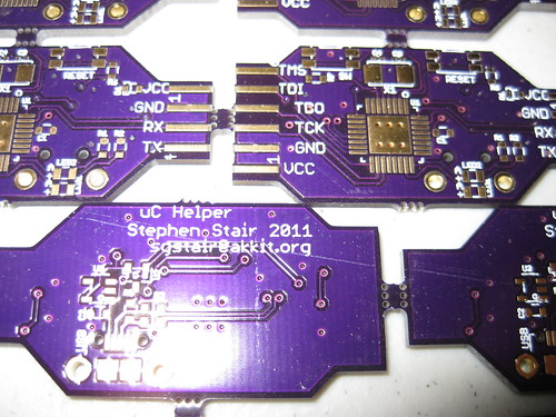
ucHelper is really just a minimal JTAG and serial interface board – Being exactly what I needed for programming and debugging here though, I got started on writing the code for it.
(more in part 3)
RSS feed for comments on this post. | TrackBack URI
March 2nd, 2012 at 4:53 pm
This looks like a lot of fun and a great project! PS, your our only hope for DSTunnel! So close!