Hardware&Projects&Uncategorized13 Sep 2015 05:00 pm

So, you’d like to write a Windows kernel mode driver? No? Well, run along then.

Curious though? Then read on.

I’ve always loved system programming – for some reason the interface to hardware is just so much more exciting and appealing than pure software API interfaces. You have a complex machine at your disposal, which can only be directed by an arcane sequence of carefully executed reads and writes to its control bits. Of course some hardware can be really exciting and fun to use (e.g. Nintendo Gameboy Advance was an excellent platform), and other interfaces can be pretty grueling and boring (My least favorite so far is the I2C hardware on the NXP LPC1342), but it’s always a great feeling to write a bunch of commands and have the hardware smoothly execute the complex maneuver you have prepared. Most of my experience in system programming has been on embedded platforms, microcontrollers, game consoles. The hardware in modern PCs is actually surprisingly similar, though because of the architecture differences, devices use DMA more often for efficient access.

It’s actually really simple to get going with a new driver on Windows – not that the system is simple, Windows drivers are very complex – they can run on multiple versions of the Windows kernel and are required to participate in some level of the system’s power management system, so there’s a lot of arcane details at play – However, there are various driver frameworks which handle all of these details for you, allowing you to focus on just the functionality you care about.

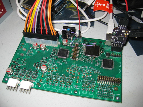
In this multi-part series I’m going to walk through the process of building a new driver (using WDF/KMDF), getting it to load on hardware (a PCI Express device), and receiving usermode requests and programming the hardware to do something. Eventually I’ll repeat this with some other frameworks (I have NDIS and Storport in mind)
This isn’t hard, but it is obscure and a bit arcane so it’s not a path that I believe is visible to new driver developers. The documentation is pretty thorough but the massive breadth of detail in Windows kernel driver development can be daunting for a newcomer.

Note also that I don’t intend to showcase all the pitfalls of driver development here, but I’ll mention some of them as they’re relevant.

One final side detail is that I’m currently employed by Microsoft. To be clear, though, this series is the product of my own time using publicly available information which I’ll try to link extensively. I’m fortunate to have had a lot of opportunities to learn these details in my work and I’m eager to make it easier for others to get started. There’s a daunting amount of information available, often written with the assumption that you’re familiar with the space (which you soon will be, given a few early steps into driver development)

So, without further delay, this is Part 1: Building and loading a driver.
(more…)

Electronics&Hardware&Uncategorized18 Jun 2014 11:51 pm

So, this hasn’t worked out quite how I anticipated so far, I’ll have to give it another go later.

You might have seen the hrv_monitor board in a picture I linked a while back – It is intended to be a simple reflective heart rate monitor. At the moment I’m unclear if I’ve badly underestimated how much accuracy I need, or if there’s some other problem with what I did that is more fixable in software…

I built a simple software stack hoping to get some data demonstrating that the device works; and what I’ve found is that the device makes a great near-range reflective rangefinder, but it’s not showing any trace of a heartbeat in my data.

So far what has been done is:

  • There’s code for the microcontroller which runs on a timer and collects ADC data 100 times a second. If the PC software is connected, it will send that data over USB.
  • I built a simple demo app which indicates its presence to the uC, and receives and graphs the data, image below. The black trace is the “dark” measurement value with no LEDs on, and the other 4 lines are the ADC values measured with each of the LEDs lit, in turn.

hrv_monitor_demo1

So well, not everything works on the first try, I certainly don’t claim to be an expert in this kind of biometric sensor and this was a very quickly thrown together side project based on assumptions and not research. Maybe I’ll still get it working though, another time – Too many other projects need attention for now.

In case anyone else is interested, the code and design files related to this project are here: https://github.com/sgstair/random/tree/master/hrv_monitor

Uncategorized07 Jun 2014 01:45 pm

I received my Kickstarter RigidBot in the mail yesterday and I’m attempting to put it together. Below are my notes from the process (this will change a bit until I’m done). I’m just using the documentation, may go back over the videos if I can’t figure something out

  • Direction the wires should face when assembling the motors is not specified. This always worries me, having assembled printers where this is vitally important.
  • Eventually it does cause problems: The extruder assembly needs relatively specific wire orientation; The wires for the thermistor and heater should come out on the fan side, and the motor wires must not come out of the bottom face. I also rotated the PCB from their diagram just in order to be able to connect the thermistor, and the thermistor wire is still a really tight fit.
  • The extruder assembly instructions not great: definitely don’t follow the steps in the order shown. I put the hobbed drive gear on backwards from their diagram so the lock screw can benefit from the keyed shaft, it seems like it will work.
  • I’m now trying to infer which of the 2 lengths of unmarked steel rods are for X and which are for Y. They only differ by about an inch in length.
  • It looks like the longest rods are used in the Gantry assembly (X axis, I assume)
  • Most everything else went together pretty simply. It’s the most straightforward 3D printer I’ve assembled so far (took less time than the printrbot simple, much less time than the mini Kossel that’s not done yet, and I never finished the QU-BD after a lot of time, it became the mini Kossel)
  • There are some gaps in the instructions. They’re possible to reason out logically/mechanically or by experimenting.
  • Reversing the extruder drive gear did cause me trouble later; I took a file to the middle of the heatsink to make things fit. Then I also filed out the attachment holes a bit further out to make them fit better.
  • I think the extruder calibration is off, and the PID values are way incorrect for the amount of power they’re applying (24V 17A supply, sheesh)
  • Most everything is working now though, will test print soon.
  • It doesn’t look like the extruder calibration is off, and it looks like the printer’s characteristics are hardcoded in the firmware
  • Test print seems to be working pretty well. The machine appears to be able to print at higher speeds than I’m used to (useful, for trying to fill that giant build volume) – I’ll have to play with settings to see what it can do.

Giant RigidBot

A few more notes now that I’ve had it running for a bit:

  • I’m not using any special print settings, just the relatively optimized defaults I was using on the printrbot. About 70mm/s max, 204C PLA, 60C bed - It’s printing surprisingly well on just the aluminum surface (I couldn’t get the printrbot to do that when I first got its heated bed working, but haven’t tried since.)
  • The fan must be forced on, or the extruder will fail horribly. I think the firmware detects the jam somehow and slows down printing? Not enough data, but neat if so.
  • The firmware seems to have a lower (than I’m used to) maximum acceleration, and there’s a lot of acceleration/deceleration ramping as a result.
  • I removed the fan grille on the extruder and replaced it with some washers, because it was blocking the fan (probably due to overtightening). The heatsink really needs to be tight against the aluminum mounting/feed block.
I am seeing some serious weirdness with printing now that I’ve tried a few more things; The print speed decreases over time.
I’ve been printing MrJaws v2 to test with, and while early layers take ~50 seconds, layers around 30 are taking around 3 minutes each, and each layer is basically the same…
I just started a new print after killing one that was going very slow, and now it’s going extremely slow on the first layer. I suspect it must be something in the firmware but I’m not sure what yet.
Circuit Design&Electronics&Hardware&LogicAnalyzer&Projects31 May 2014 01:23 pm

I’m making a concerted effort again to post more often, we’ll see how it goes this time…

First a few quick notes about a few other things I’m working on that will probably see posts in coming weeks:

  • I’m nearly done building a Kossel Mini 3D printer. Related, not too long ago I worked with a friend of mine on a simple board to monitor force-sensitive resistors for bed leveling calibration, see his writeup here.
  • Caught the bug to build a 2-wheeled balancing robot; I’ve seen too many of these again lately… Only this time I have an electronics platform that can be easily repurposed for this project.


So, exciting times! The Logic Analyzer boards came back from OSHPark all pretty in purple as usual. It’s been a while since I did any serious PCB assembly but I still seem to be pretty good at it :)

Logic Analyzer rev1 PCBs

Freshly Baked LogicAnalyzers

This weekend, among other things I’ll be getting started on blinking some LEDs and making sure these boards work the way they should. More on this (and the other reflowed project pictured) later!

Electronics&Hardware&Projects17 May 2014 12:21 am

… At least not nearly quickly enough.

So, I have been pretty busy since my last post, but I don’t really have a whole lot to show for it.
The quadrotor project I talked about last has mostly been shelved for now, pending some other work investigating motor control in general (I’m mainly interested in stepper motors, but brushless motors are very similar), and all of that has been behind some other work, not all of which I’m ready to talk about yet. Relatively soon, though.

One other project that’s very important to me which saw some big progress recently is a Logic Analyzer project. The first big milestone has just been hit - I completed the circuit board design last weekend.
This project is intended to be like a swiss army knife, a multitool of digital electronics development and reverse engineering; Fundamentally it’s a high speed USB link to an FPGA controlled from a PC. The top things I want from it are:

  1. Logic analyzer type functionality
  2. Useful building blocks for in-system programming and testing; JTAG, SPI, etc, so I can wire it up to my stuff and program in a uniform way. Also without losing the logic analyzer functionality.
  3. Useful building blocks for reverse engineering; Being able to dump various kinds of flash, usable for characterizing systems, detecting jtag/etc ports.
  4. Platform to build more complex devices on; I can reuse the stack to make other more specialized USB connected devices quickly.

It’s a wildly ambitious project, and I’m building it mainly for myself with the things I want; however I’m making the design open if anyone else wants to follow along or try it out (or improve it!). Check it out if it sounds interesting at: https://github.com/sgstair/logicanalyzer – It will surely evolve over time, hopefully into something useful.
Once the PCBs come back for the logic analyzer and as I get further with the software/firmware I’ll be posting pictures and more details about how it goes. It should be a pretty fun project.

I did finally get tired of not having a 3D printer up and running (my electronics solution will still take some investigation time, and it still isn’t a top priority); and after the frustration of receiving an .. ehm … “mechanically challenged” 3D printer from a kickstarter project, I finally bought a printrbot simple v2, which has been working rather well, even more so with some upgrades like a heated bed. It’s really pretty amazing to be able to design a part and then iterate on the design several times over an afternoon to produce something that works well quickly. I still see a lot of problems I want to fix in the 3D printer space though, and will try to fix them. eventually…

There are some more things in the pipeline too, but I shouldn’t say too much or I’ll run out of things to post about again ;)


Electronics&Hardware&PCB Layout&Projects19 Oct 2013 12:15 pm

This isn’t exactly what I had in mind with my last post (there’s another project coming up after this one), but it’ll do for now :)

I had an idea for a simple mechanical design for a quadrotor, and since I was already pretty interested in building one, that prompted me to go work on the design for it. Like with many things I do, I like to build the full stack in projects like these – so I’ve designed my own electronics for it as a first step. Some of the PCBs have come back from fabrication so I expect to make more progress with this pretty soon.

Some pictures from the PCB designs:
quad_esc_r1

quad_main_r1

quad_nrf

The three boards above are a speed controller to drive the motors, the main PCB that will collect sensor data and do control, and a plug-in module for the main PCB which has wireless (via Nordic RF chipset) and a flash chip for archiving sensor data / other general use.

For now, I’m just writing initial firmware and testing that things work, but once I confirm the design is viable I’m planning to release the design files for it.

Another interesting feature of this project is that I screen-recorded the PCB design process – I’m planning to edit the videos into timelapses and add some commentary on the thought process behind the design. I’ll post about these also once they’re released.

Electronics&Projects&Uncategorized17 Sep 2013 08:58 am

Well! It’s been another year since I posted anything; not the first time I suppose.
I’ve come up with an idea for something I want to do though, which will result in a lot of blog posts in about a month or so. I don’t want to say too much about what it is yet, but keep an eye out for it :)

Electronics&Hardware&Projects26 Aug 2012 07:11 pm

I am really bad at keeping to a schedule with this blog :)

It was going so well, with the 3D Printer posts, all good posts and not too far apart, and then… nothing.

I did continue to work on the 3D printer a bit past that, and will resume those posts again, probably once I have everything working – it’s still waiting for some software development which I have been stalling on / doing other things.

So, what has been taking my time? Let’s see…


Reflowed: nRF_stick, chopper1, nRF_sensor1

First I messed around with some Nordic RF chip stuff (I’ve built some infrastructure, but these projects are still ongoing)


IMG_0893.JPG

I built some PCBs for an RGB POV spinning top, which still hasn’t been fully assembled or programmed…


Reflowed: psplcd

I designed a board to control the PSP LCD, and finished its software (it works!) – I normally do everything but a friend of mine did the PCB layout on this board.


GBCart: Nintendo logo

And most recently I’ve been working on a gameboy cartridge. Not much to say about this one yet, but will be fun when there is :)


And of course a few other things along the way; my Flickr Stream has more, and is usually the first place new stuff shows up.

Feel free to ping me with any questions or comments! I’ll try to post a bit more regularly.

Circuit Design&CNC Controller&Electronics&Hardware&PCB Layout&Projects04 Feb 2012 10:58 am

Armed with a blinking LED program, I set to work attempting to flesh out the rest of the software for the CNC board. I built and tested a nested vectored interrupt handler, and started trying to port my USB stack from another chip that has very similar USB hardware. As time went on though, the outlook became a bit bleak; A number of things did not appear to be working as intended on this chip, and the manufacturer’s example code included bizzare comments and workarounds for some pretty impactful bugs that weren’t otherwise documented. Not confident that I would be able to make this chip work the way that I wanted, and being less than thrilled with the ease of assembly and some of the design of the CNC Rev1 board, I decided to make a new CNC board.

My design goals would be:

  • Ensure the design will work, by using chips I’m familiar with & already have code working on.
  • Reduce complexity by only having one motor driving voltage, but still allow that voltage to be changed.
  • Reduce the part count per motor, by consolidating components into fewer packages and taking a different design path driving the motors.

(more…)

CNC Controller&Electronics&Hardware&Projects31 Jan 2012 12:31 am

As I mentioned earlier, JTAG is a pretty simple protocol. For the ucHelper I’ve designed a command-oriented serial protocol that allows me to perform various JTAG and UART operations. After some initial trouble with physical connections on the CNC board, it was possible to enumerate the JTAG chain! In order to be sure JTAG was really working as intended, I took a short detour and wrote an SVF player, and was able to program some existing Xilinx FPGA boards from SVF files (like serialeth).

The ARM Chip I was using on the CNC board (NXP LPC2927) has two JTAG chains – one of them is a boundary scan / flash (and who knows what else) chain, and the other is for the ARM9 standard debug interface. I only really wanted to program the flash, so I started out with the flash chain – There was some documentation for the JTAG flash interface of a previous chip in the series so I was hopeful this one would be similar.

Unfortunately it was not meant to be. The enable bits / initial handshake sequence for the flash controller on this chip seems to be entirely different than the earlier one, sometime I may go back and find the right bits to make that work, but I shifted my focus to using the ARM debug interface. The first thing I noticed, is that it didn’t work :) As it turns out (after connecting the layers of deep indirection in the documentation), you must have a crystal in a specific range of frequencies for it to work; After fixing that though, I began to make progress on that front. the ARM debug interface for this chip is relatively well documented in the ARM9 documentation on ARM’s site. Documentation always seems to leave something to be desired, but this was at least relatively unambiguous – and worked!

Effectively, the ARM9 chips (also most other ARM chips), for a debug interface, simply intercept the processor’s instruction and data busses, and allow you to single step the processor. So you can perform operations by injecting the instruction you wish to execute, and single stepping. You can write a register to an arbitrary memory location, which causes it to be intercepted on the data bus (afterwards you can read the data bus) – Similarly you can read from memory and it will end up reading the value you insert onto the data bus into a register. It’s a rather minimal and effective debugging interface, it doesn’t consume much in the way of hardware resources, though the software to do anything useful with it has to be a bit complicated as a result.

Since the single step operations capture the data bus, it’s not possible to directly modify or read system memory through them, but there is another special provision for doing this, for executing individual instructions synchronized with the normal CPU clock that can interact with memory. So, I wrote a handful of wrappers that would allow me to manipulate the CPU’s registers and read from / write to memory, and around that built a small program that wrote the flash using the system’s internal flash controller.

With that literal pile of work behind me, I set off building software for the ARM chip itself. A short amount of time later, I had a blinking LED (Because this is naturally the most important thing to do with /any/ piece of hardware)

IMG_0826.JPG 

(Not visible: LEDs blinking)

(Continuity note: Note that the above board is not the same one as the board shown in part 1! At some point in messing with the JTAG chains I became sufficiently frustrated with the quality of connections on the first board, which had been reworked a few too many times perhaps, that I built a second board and took special care in making sure the JTAG chains and other important connections were in good shape. It’s a bit less than fully populated because… placing some 400-500 components is HARD!)

(More to come in part 4…)

Next Page »